If we link two points of a curve with a chord, we name “sagitta” (f) the
distance from the center of the chord to the intersection point between the
perpendicular to the chord and the curve.

If we take always the same chord length and we measure the sagitta in its
center, the same sagitta will correspond always to the same radius.
If we consider the straight-line as a curve with infinite radius, its sagitta will be “0”.
If we know the length of the chord and the length of the sagitta, we can likewise calculate the radius of the curve.
Formulae of the chord, arc
and sagitta
In a circumference of center O and radius R, we draw
the chord AB =2c, being M the mid-point of such chord.

The diameter drawn CMOD
is perpendicular to the chord AB in the point M, being the sagitta: f = MC
Using the triangle similarity: CMB and DMB
CM/MB = MB/MD ;CM*MD = MB*MB
And replacing values: CM
= f; MD = (2R - f)
Therefore: C 2=f*(2R-f)= 2*R*f – f 2
In railways, the radiuses of the curves are very large with
regards to their sagittas, since we use chords of 20m, and therefore we can
disregard the term f 2:
C 2=2*R*f
f = C 2 /2*R
For chords of 20 m, c = 10 m. We obtain:
f = 50 /R or f = 50.000/R (f in mm, R in mts)
The relation between the length of the arc (S), the sagitta (f) and the chord (C) is as follows:
S=2*((f/2)+(C2 /(2*f)))*ASN ((8*f*C)/(f 2+ C2 ))

In the curves, the train circulates guided by the outer rail,
also known as driver-rail, in which the flange of the wheel attacks the rail
with an angle variable as a function of the curve radius.
In order to avoid abrupt direction changes, the curvature
must be uniform.
Abrupt direction changes caused by significant curvature
differences will entail knocks in the rail that little by little will cause
deformations in the railway and, the bigger the deformation, the bigger the
knock, making the deformation grow exponentially.

Since the sagittas of the curve will indicate its curvature,
their values must be identical in the circular curve, and the variation
required when passing from straight-line to curve (or reversely) must be smooth
and progressive.
Using the clothoid as transition curve, in which the main
property was that its curvature is proportional to its length, we ensure a
uniform progression for the sagitta changes.
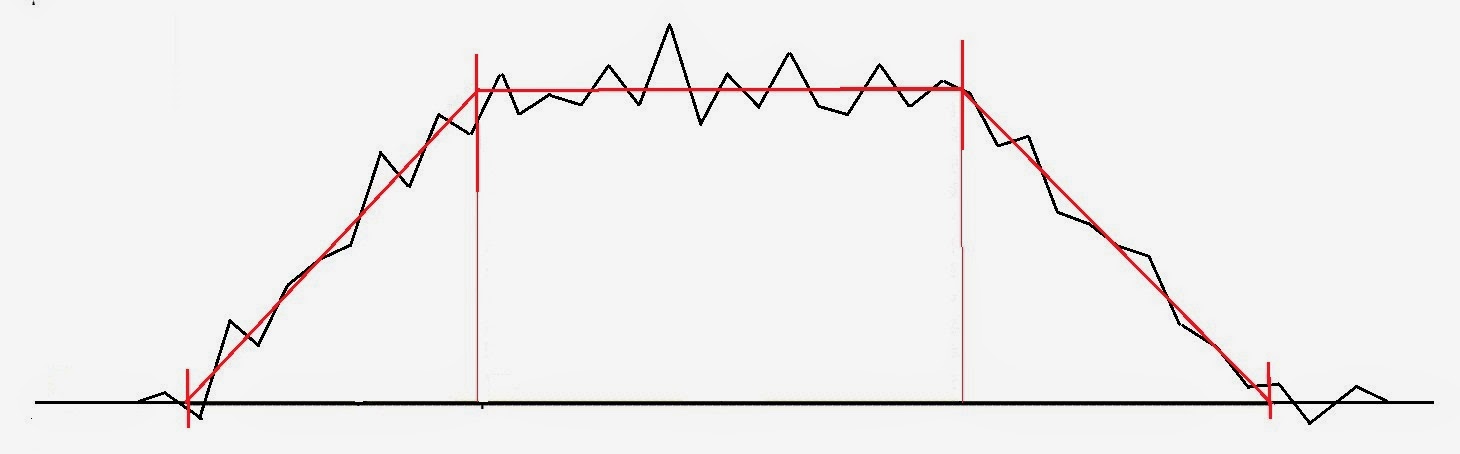
A curve can be represented, as commented before, by its
sagitta diagram, and its perfect status would have the following shape:

In the circular curve the sagitta will be equal in each of
its points, and in the transitions it will be increasing or reducing progressively.
In the railway,
deformations in the curvature occur with the course of time and motivated by
the
following factors:
following factors:
- Circulation at inappropriate speed
- Dilatations due to temperature changes
- Ballast-base displacement due to rainfalls
- Etc.
These deformations cause consequently variations in the
sagittas, so the sagitta diagram can become something like:
This correction process is also known as “Curve straightening”.
The process of curve straightening must be carried out, not only for the maintenance of a ballasted railway, but it is also essential to carry it out before pouring the concrete on a ballastless (concrete slab)-railroad, in order to “round off” the polygonal-path that we have created in a coordinates setting-out so that we minimize the assembly-mistakes.
It will be composed of the following phases:
1.- Field work
- Measurement of the railway
- Data collection from existing references.
- Alignment of adjacent lines.
- Sagittas of a curve
- Manual or computer straightening
- Calculation results in paper.
- Place the calculation data in the respective references
- Submittal of the calculation results to the staff responsible of maintenance with heavy machinery.
GO TO CHAPTER VI- Straightening of Railway- Field work
Full themes in the book -In paper and ebook (Follow the link)

----------------------------------------------------------------
INTRODUCCIÓN
Si unimos dos puntos de una curva con una cuerda, denominaremos flecha a la distancia que hay entre el centro de la cuerda y su perpendicular en la curva.
Si tomamos siempre la misma longitud de cuerda y medimos la flecha en el centro de esta, a un mismo radio corresponderá siempre una misma flecha.
Si consideramos una recta como una curva de radio infinito, su flecha será “0”
Si conocemos la longitud de la cuerda y la medida de la flecha, podemos conocer el radio de una curva.
Repaso de fórmulas
En una circunferencia de centro O y radio R, se traza la cuerda AB = 2c, siendo M el punto medio de dicha cuerda.
El diámetro trazado CMOD es perpendicular a la cuerda AB en el punto M, siendo la flecha: f = MC
Por semejanza de triángulos: CMB y DMB
CM/MB = MB/MD ; CM x MD = MB x MB
Reemplazando valores: CM = f ; MD = (2R - f)
Luego: C 2 = f x (2R-f)= 2Rf – f 2
En ferrocarriles, los radios de las curvas son muy grandes en relación a las flechas, pues se utilizan cuerdas de 20 m, pudiendo despreciar el término f 2
C 2= 2Rf
f = C 2 /2R
f = 50 /R o bien f = 50.000/R (f en mm, R en mts)
La relación entre la longitud de arco (S), la flecha (f) y la cuerda (C) es la siguiente
S=2 x ((f/2)+(C2 /(2 x f))) x ASN ((8 x f x C)/(f 2+ C2 ))
Para que no existan cambios de dirección bruscos, la curvatura debe ser uniforme.
Los cambios bruscos de dirección motivados por una diferencia de curvatura importante producirán golpes en el carril que poco a poco irán deformando la vía y a mayor deformación, mayor será el golpe y la deformación se hará exponencial.
Como las flechas de la curva nos indican su curvatura, estas deberán ser uniformes en la circular y la variación necesaria al pasar de recta a curva o viceversa deberá ser suave y progresiva.
Utilizando como curva de transición la clotoide, que entre sus propiedades está la de que su curvatura es proporcional a su longitud, nos aseguramos la progresión uniforme en el cambio de flechas.
Una curva se puede representar por su diagrama de flechas, y su estado perfecto tendrá la siguiente forma:
En la circular la flecha será igual en todos sus puntos, y en las transiciones irán aumentando o disminuyendo de forma progresiva.
- Circulación a velocidad inadecuada.
- Dilataciones por cambios de temperatura.
- Descalces del balasto por lluvias.
- Etc.
Se producen deformaciones en la curvatura y por lo tanto una variación en las flechas, de manera que el diagrama de flechas puede quedar de una forma similar a este:
Como las diferencias en la curvatura harán que cada vez se vayan incrementando las deformaciones más rápidamente, es indispensable que periódicamente se corrija la curva para volverla a su estado primitivo.
A este proceso de corrección lo denominamos “Rectificación de Curvas”.
El proceso de rectificación de curvas se debe realizar, no solo para el mantenimiento de una vía sobre balasto sino que también es indispensable realizarla antes de hormigonar una vía en placa, para “redondear” la poligonal que hayamos creado en un replanteo por coordenadas.
Consta de las siguientes fases:
1.- Trabajo de campo
- Medición de la vía.
- Toma de datos de las referencias existentes.
- Alineación de las rectas adyacentes.
- Flechado de la curva.
2.-Trabajo de oficina
- Rectificación manual o mediante programa informático.
- Obtención en papel de los resultados del cálculo.
3.-Materialización del trazado rectificado.
- Colocar los datos de cálculo en las referencias.
- Entrega a los responsables de mantenimiento con la maquinaria pesada de los resultados del cálculo.
IR A CAPÍTULO VI - Rectificación de Curvas Ferroviarias - Trabajo de campo
Temas completos en el libro - en papel y ebook (Siga este enlace)

No hay comentarios:
Publicar un comentario